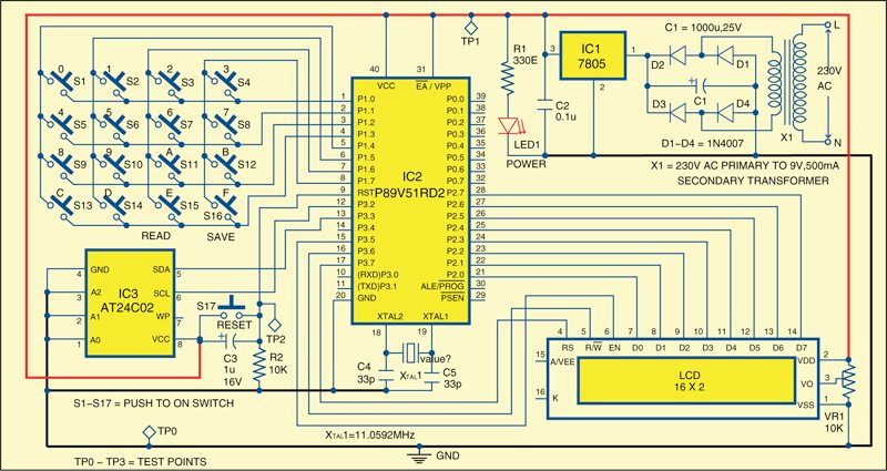
- #SPI SERIAL FLASH PROGRAMMER SCHEMATIC CAPTURE SERIAL#
- #SPI SERIAL FLASH PROGRAMMER SCHEMATIC CAPTURE SOFTWARE#
I hope you did power budget calculations - that AMS1117 LDO is fine if you use the genuine part. OTOH, you should probably increase that 10u input capacitor for the voltage regulator, 10u is really low for any sort of bulk capacitance on the board.Īnother thing to consider would be to add a pull-up resistor to the reset lines of the sensors, otherwise you may get a nasty surprise when they will reset randomly while in use.
#SPI SERIAL FLASH PROGRAMMER SCHEMATIC CAPTURE SERIAL#
That's a generic USB to serial bridge, if ESP32 can be programmed over UART then I don't see why it couldn't be programmed using this. That could well cause problems at higher I2C speeds. That said, your 10k pull-ups are very likely too weak, depending on the length/capacitance of the traces to the sensors. I2C is an open collector/drain bus, there must be only one set of pull-up resistors. I also don't know why you would need the button for GPIO0 since you already have the auto-reset circuit. If never used the ESP's JTAG interface so I can't tell if that's right.

Not sure if that's intentional but it's certainly not necessary. You have two 0.1uF capacitors on your ESP's EN line (one by the ESP and one by the button). The Arduino IDE uses the ESP's vSPI interface (IO5 = SCK, IO18 = MOSI, IO19 = MISO) for its SPI library. Pins 17-22 of the ESP are connected to its onboard flash memory and should therefore not be used. nINT requires an external pullup resistor (4.7k) if you intend to use it.ġ0k pullups for the I2C lines are quite high for a 3.3V design (although almost certainly fine), maybe switch to 4.7k or 3.3k. Furthermore, pins 4 and 5 of the CCS811 must be connected, so I'd tie them together and just use one testpad. IC2 is just 5 TVS diodes in one package, so there's no need for a decoupling capacitor.Īccording to the datasheet of the CCS811 nWAKE must be held low while communicating with the sensor, so you should probably connect it to the ESP or tie it to GND permanently if you don't need the CCS811's sleep functionality. R10 seems quite high (only ~130uA even at a low forward voltage of 2V), but that highly depends on the LED you are using (some types may still be sufficiently bright with that little current). Thanks in advance! Sorry if this is the wrong place to ask. Would a simple switch at the beginning not cause any problems turning the circuit on and off? Has anyone had much success using the CH340G chip for programming the ESP32? As I hopefully want to use the Arduino libraries to program this chip on the board. While the flash chip uses SPI which, if I am correct from my research does not use any pull-up resistors. The two sensors both share I2C, SDA & SCL lines and share common pull up resistors, will this cause any problems? However, I feel like I might be missing out on something, and would be very grateful if someone good gives any feedback or advice on the Schematic. I have looked through the datasheets and various examples for each component. I have also added test points, which I may use on the PCB for testing or using a pin I may need.
#SPI SERIAL FLASH PROGRAMMER SCHEMATIC CAPTURE SOFTWARE#
In quad mode, the software automatically distributes the data bytes among the IO lines using the same bit pattern depicted in Figure 8 above.I am pretty new to designing schematics & PCB's and have designed a circuit with an: ESP32, Temperature/Humidity sensor, CO2 sensor, USB to UART, Flash, and a power regulator. Note that we’re changing from 4-wire mode to quad mode in the middle of the transaction.

Wt AA AA AA 00 // Write 3-byte address and 8 read mode bits Compare this to the 16 clock cycles required for our simple read transaction and it’s easy to see why quad mode is gaining popularity for high speed flash memory applications! To create this sequence in the SPI Exerciser command language, we would use the example code: 4m // Start in 4-wire mode Quad mode fast read sequence for Spansion S25FL016K or equivalentĪfter the address cycle and dummy bytes have been sent by the host, the component begins sending data bytes each clock cycle consists of a data nibble spread across the 4 IO lines, for a total of two clock cycles per byte of data. JTAG Boundary-Scan & JET Technology Benefits FAQįigure 8.On-site JTAG Boundary-Scan Training Classes.Test Genie: Turnkey Boundary-Scan Solution.


 0 kommentar(er)
